Pharmakeyboard_arrow_rightWhite Papers / Managing Ready-to-Use (RTU) containers in aseptic production facilities: a path to efficiency and compliance.
menu

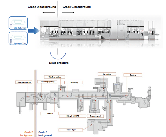
This white paper explores the challenges of integrating ready-for-filling containers (vials, syringes or cartridges) and their respective packaging system, also referred to as tubs or trays, into high-speed aseptic production lines, emphasising how this approach can significantly enhance operational efficiency, promote sustainability and drive innovation in aseptic processing environments. This analysis document aims to evaluate the logistics, handling and management of RTU packaging and how these aspects impact the management of classified areas while maintaining sterility requirements for primary packaging. This paper covers the entire journey, from the unloading of stored and transported pallets in the receiving incoming dock to the opening of tubs and trays within the aseptic filling line (grade A area).
By examining essential factors such as batch sizes, filling throughput rates and smooth transitions between facility zones and cleanroom classifications, it is possible to identify the benefits that this packaging system and relative management strategies can bring to aseptic productions and injectables’ sterility assurance. Specific considerations are present for critical processes like storage, unpacking, and quality controls of the packaging system to maintain the primary container integrity and sterility.
This paper illustrates cutting-edge methods for transporting the packaging system through various facility zones, from non-classified (NC) receiving areas to classified clean rooms (D, C or B grades), where the aseptic filling line begins. Here, sanitisation and bio-decontamination processes could play a vital role in reducing the bioburden on packaging prior to the fill-finish line. In aseptic isolators or RABS grade A areas, handling tubs may involve advanced decontamination systems such as E-Beam, VPHP or debagging solutions “No-Touch Transfer” (NTT), each one offering distinct advantages and challenges in sterility assurance, cost-effectiveness and operational efficiency.
This document aims to provide a GMP-compliant quick-start reference that streamlines material flow and leverages automation to boost productivity and mitigate contamination risks. This analysis provides a comprehensive look at the diverse solutions available for managing RTU containers in aseptic facilities, supporting decision-makers toward practices that promote efficiency, compliance and sustained innovation.
Reference standards
Guidelines and references
In the past world of aseptic filling lines for sterile parenteral drugs, production facilities relied heavily on traditional bulk processing. Large quantities of vials, syringes and cartridges used to arrive in bulk and needed to be washed, sterilized and depyrogenated before being filled and closed in an adequate aseptic environment.
With the advent of Ready-to-Use (RTU) containers already in in the 1980s with PFS (pre-fillable syringes) and proceeding with the introduction of vials and cartridges starting from 1st half of 2010s) pre-sterilised in packaging system able to maintain the sterile barrier up to the point of use in the filling line. This breakthrough transformed the workflow because ready to fill/use containers eliminated the need for in-house sterilisation, reducing manual handling and streamlining the entire process. RTU’s suppliers will guarantee the process including contamination control strategy for particles and microbiological aspects including sterilization, which is beneficial for the end customer. The ability to remove the primary container sterilisation process from filling facilities has been a transition increasingly adopted over the years; this approach has been mainly applied in the pre-filled syringe (PFS) sector, as well as for cartridges or flexible “combo” lines with low to medium speed. These flexible lines are primarily used by CMO/CDMOs to quickly adapt the production environment to different market demands.
The push for increased use of this RTU/RTF container-based approach has driven a shift from limited applications, involving small batches and without extreme production speed requirements, to high-speed production scenarios within long-duration campaigns typically consisting of multiple batches on large fill-finish manufacturing plants.
This transformation, which has scaled both productivity and facility layout amidst a regulatory push from authorities to strengthen requirements for sterility assurance, has led to a series of logistical and operational challenges by highlighting a range of limitations present in many production sites and traditional filling lines.
In a high-productivity scenario for injectable products, main examples include the production of widely distributed small molecules, antibiotics, large-scale single-dose PFS vaccines, insulin medications, recent obesity drugs, mainstream biologics like monoclonal antibodies or blood-derived products. In these facilities, we traditionally find formulation processes capable of handling 1,000–2,000 litres of drug product per batch across multiple tanks, serving filling machines with productivity rates between 24,000 and 36,000 units per hour. Production batches can reach 300,000 – 400,000 doses within multi-batch campaigns spread over several weeks and easily surpassing one million doses in total. This type of facility achieves an annual productivity of between 100 and 200 million doses and they represent the state of the art for large-scale injectable production. Given the required productivity, the demand for a tub packaging system is a direct consequence. Considering a tub holding 100 syringes, a batch of 200,000 – 300,000 pre-filled syringes (PFS) would require the storage and handling of 2,000 – 3,000 tubs during production. In a campaign scenario with multiple batches, logistics and material introduction, procedures may need to manage 10,000 – 20,000 tubs containers over a span of 2 or 3 weeks.
Starting from these initial considerations, it is possible to identify the main challenges that production sites will need to address
The process of introducing RTU packaging into an aseptic facility involves multiple steps each of which can be executed differently depending on the chosen strategy for sterility assurance, the configuration of the production cleanroom and layout, and the potential to implement automated or semi-automated solutions. For a comprehensive analysis it is therefore necessary to break down the main steps of tubs or trays handling the process and examine each element in this chain by assessing variations and possible alternatives.
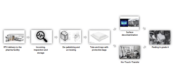
Figure 1: RTU path to grade.
The flowchart therefore describes these individual steps with the starting point being the arrival of the pallet at the external unloading area of the production site, carrying a defined number of tubs in accordance with supplier specifications and, if applicable, customer requirements.
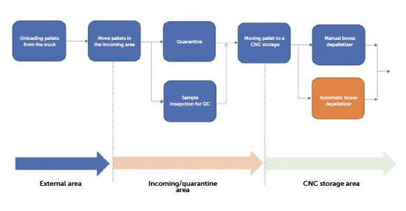
Figure 2: workflow steps from delivery to de-palletizing.
The standard pallet provided by RTU manufacturers is configured to provide space for a specific number of boxes, each one containing tubs or trays provided with their protective bags (single or double layers). The polypropylene boxes can be arranged on the pallet in various patterns to maximise space utilisation and, in some cases, the load weight distribution. For example, one of the RTU vials pallets provided by a very specific supplier for in-nest (tub) containers contains 12 boxes (each layer has 4 boxes in the standard Stevanato Group packaging). Each box instead holds 15 tubs arranged in rows of 3, positioned upside down from the top opening of the box.
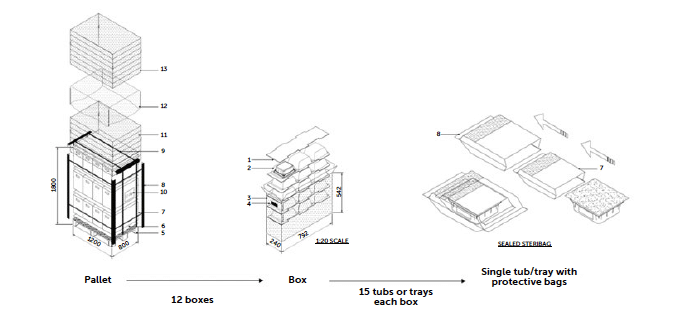
Figure 3: packaging structure.
Like any critical element in the pharmaceutical production process, the materials undergo an incoming inspection involving document verification and, if necessary, specific in-situ quality checks. The pallet is then stored in the quarantine area as material under inspection and will move to compliant material storage only after passing inspection. The RTU supplier also provides documented evidence verifying the product’s quality. Total transit time can vary from a few days to two weeks.
Below is a brief list of incoming procedures that could be requested:
The tests and incoming verification strategy can be defined between the RTU supplier and the end customer. The statistical sampling strategy usually follows ISO 2859 for sample definition, and a list of tests can be established for independent execution by the customer or delegated to the supplier. In the case of delegation, the supplier will conduct the control tests and provide the corresponding documentation upon shipment.
Optimisation note: It is possible to request suppliers that some RTU packaging as tub or tray be provided separately in dedicated boxes collected randomly or according to the customer’s request. This allows for inspection tests without compromising the pallet, thereby simplifying logistics management before formal approval. Containers for sample testing are agreed upon between the customer and the RTU supplier based on the customer’s incoming control strategy.
In the proposed large-scale production simulation, the number of pallets stored could reach between 10 and 20 units per production batch. This number increases when considering the total campaign duration, with the possibility of managing 50–100 pallets entering the facility each week. Since the number of pallets in a large-scale production setting becomes significant, it is necessary to analyse how the depalletizing process can be performed efficiently. Due to their size, weight and contamination risk, pallets cannot be transported in classified D and C areas. In some cases, wooden pallets are replaced with steel or plastic alternatives that are easier to clean, facilitating movement toward classified areas for packaging handling. As the packaging can be protected with shrink wrap and cardboard corner supports, the boxes are removed and the depalletizing process completed before moving the material into classified areas.
Optimisation note: The depalletizing process can be performed manually or potentially assisted by robotic solutions that open the outer layers, remove protective cardboard, and singularise the boxes, placing them onto a conveyor belt that then transports them to the facility’s classified areas. This approach is still not widely adopted but is used in some facilities to eliminate all manual handling. Standardisation of the pallet allows for an automated approach, and it is possible to coordinate specific requirements with the RTU supplier to improve product machinability.
Once removed from the pallet, the individual box can be transferred into a classified environment. To avoid the accumulation of dust and particles, after the depalletizing process, it is advisable to transfer the material through appropriate Material Airlocks (MALs) into a lower-contamination zone and store it there before the final transfer to the filling line. The polypropylene boxes are then sanitised and cleaned with classic IPA and biocidal products.
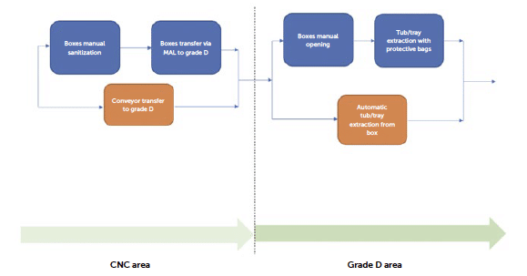
Figure 4: workflow steps for un-boxing.
Optimisation note: The transition to a grade D classified environment requires an operational procedure, typically manual and usually not supported by automatic VHP or UV decontamination MAL. Given the transit time, the incoming material flow will follow the pace of the production process. A high-speed line may require the intake of 5 to 6 tubs per minute, translating to 300 – 360 tubs per hour and consequently 20 to 24 boxes per hour. Therefore, the material flow should be managed with sufficient time for MAL transit and sanitisation or fully stored in the classified area before the start of the production batch.
The box stored in the classified area can now be opened to allow the extraction of the individual polymer tub or tray. RTU containers are provided placed within a polymer tub which is covered with a plastic sealing lid thermo-welded by heating. Once sealed, the tub and/or tray and lid assembly serve as a barrier system that is intended to maintain the sterility of the contents following sterilisation of the entire primary packaging assembly. The bagged, tubbed and nested primary packaging assembly is then packed into a single or double protective bag. As the primary container approaches the sterile environment, the protective layers are removed, inevitably exposing the container to risks of tearing or breakage. At this stage, it becomes more critical to handle the container carefully, both due to the controlled contamination environment of the classified area and the potential breakage of the protective packaging of the RTU packaging. This packaging is essential for ensuring, as will be discussed in the case of isolator and RABS entry strategies, the low bioburden of the tub or tray’s outer surface.
Optimisation note: An automated management strategy for this phase becomes valuable not only in terms of productivity but also as a solution for risk reduction. The approach for un-boxing the RTU packaging with protective bags is usually manual, but automated solutions are available in the market. This automated solution can execute the un-boxing using anthropomorphic robots and load the tub/tray in the fill-finish line. However, automated solutions for managing this phase still remain uncommon, because the complexity involved in automated debagging, as seen in typical NTT processes, often requires operator supervision when loading tubs or trays onto the equipment. Usually, the protective bags have to be stretched and pre-unfolded before the loading operation in the fill-finish line, which is a not an easy-to-automate procedure.
An inspection phase can be suggested after the removal of the protected tub or tray from the box. Due to the criticality of bag integrity, which guarantees the low bioburden of the external tub/tray surface, a possible failure of integrity could lead to the failure of the final transferring process inside the isolated grade A area. An inspection approach can be completely visual and provided by an operator, who could inspect the external bag integrity. The protective bag must be unfolded and flattened, and after this handling the operator should visually check integrity by inspecting the bag from both sides. The trained operator also checks if there is damage to the shape of the RTU packaging due to possible problems/damage occurring during road transport.
Figure 5: workflow steps from box to single tub or tray bags protected.
Optimisation note: Specially designed protective bags with improved robustness and an additional visual inspection feature for perfect sealing are available on the market and it is possible that in the near future an automatized visual inspection system may provide a check of the bag protected packaging before introducing it into the fill-finish lines. An alternative strategy is to avoid accurate bag inspection, due to the supplier’s assurances, qualification of transport logistics, and sample-based inspection controls can justify the absence of in-line inspection procedures for the tub or tray once it is removed from its box. Additionally, when combined with introduction methods involving surface decontamination (e-beam, VHP or pulsed light), the risk of protective bag integrity failure and consequently a potential contamination of the aseptic area is further minimised.
In defining the facility layout, different approaches are possible, each with significant impacts on the overall footprint of the production area. The first approach (case 1) involves installing the filling equipment, including areas where the automatic or manual bag removal process takes place entirely within grade C. Since regulatory requirements stipulate that an open isolator (equipped with mouse holes protected by a pressure cascade) must be installed in grade C, one solution is to have the entire fill-finish line, including debagging chambers, within the grade C cleanroom. Alternatively, it is possible to maintain only the “aseptic core”, the grade A isolated area where the aseptic process occurs, in grade C background, while positioning the initial debagging phases or the line introduction point in grade D (case 2).
Introducing RTU packaging from grade C (case 1) could bring these advantages:
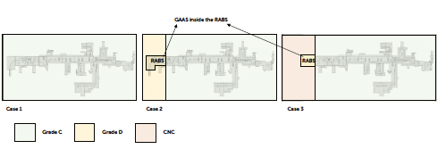
Figure 7: different layout and classification strategies.
Optimisation note: Considering the presence of double protective bags or a surface decontamination system for the RTU packaging, the risk of contamination remains very low. Additionally, in large-scale production, introducing multiple tubs or trays into grade C requires greater effort for cleaning and sanitising incoming materials, in an operational context where both gowning procedures and process speed are critical. In a high-speed facility, the operator must position tubs or trays with their protective bags onto the line’s transport system within 12 to 15 seconds, maintaining a challenging pace throughout the production period. The presence of limited buffers, without the possibility for significant accumulation, does not support the careful attention required for proper procedures to minimise particle release in the classified area. For these reasons, if sustained by the contamination control strategy, it is advisable to design the facility layout to allow material introduction in grade D/CNC, avoiding the need for transportation, sanitisation and handling hundreds of tubs or trays in a high-classification grade C area.
There are different types of surface decontamination technologies. Here is a list of the most common:
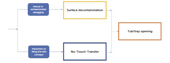
Figure 8: workflow steps from single tub or tray “bags protected” to grade A area.
From the perspective of No-Touch Transfer systems, there are solutions at various levels of
These current technologies have their own advantages and disadvantages.
A No-Touch Transfer (NTT) approach for opening a bag protected tub or tray is designed to maintain sterility and minimise contamination risks by avoiding direct human contact with the primary container. Here’s how a typical NTT process unfolds
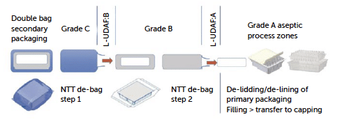
Figure 9: from “No-Touch Transfer: pre-sterilised container entry into EU grade A filling environments following GMP and QRM principles” by J. L. Drinkwater, D. Novak, T. Eaton, B. Hare “.
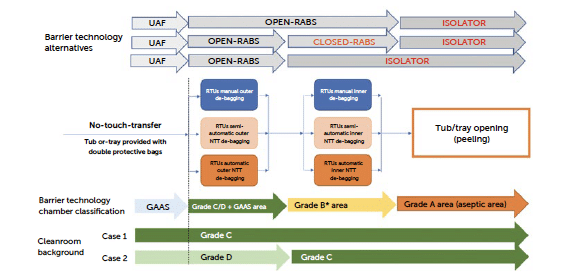
Figure 10a: workflow and barrier technology configurations for No-Touch-Transfer.
Note for grade B*: transfer solutions from grade C with GAAS directly to grade A are still possible if properly justified in the process CCS. As reported by some U.S. manufacturers (reference: Grand River Aseptic Manufacturing presentation at the ISPE Pharma 4.0 and Annex 1 conference 2023), authorities have required a reclassification from Grade C to Grade B in the area where the inner layer was debagged, inside a new aseptic fill-finish plant. For this reason, although still justified in some European and American manufacturing sites, regulatory pressure is moving toward a solution that includes a higher-classified environment. The NTT process can be implemented with various types of automated solutions, allowing for either an assisted approach, where the operator partially intervenes, or a fully automated approach, where the operator is not involved, and the entire process is managed by the automated system. In a high-speed setting with process times between 12 and 15 seconds, it is advisable to have a fully automated system to avoid bottlenecks created by one or more operators on the line. The NTT concept is inherently challenging in a manual context and encounters limitations when operations must adhere to demanding cycle times. In such environments, gloves manipulation and a cycle time of only a few seconds (5 or 6 tubs per minute) complicates the requirements of a low particle contamination.
Optimisation note: The possibility of avoiding issues with automatic debagging and peeling systems (removal of the tub cover) is a development priority both for machine manufacturers and RTU suppliers. Packaging design has been improved over time to simplify and automate these processes, and the experience gained by machine manufacturers and suppliers has made the process robust and repeatable. Solutions such as pre-heating systems for the tub or tray before opening can significantly reduce the risk of layer breakage during the peeling operation.
The barriers used to protect the debagging process can also have different configurations. First, the process can be performed in various background environments, requiring greater attention to at least RABS solutions when the tub or tray introduction process occurs in grade D. At the same time, NTT design involves maintaining a pressure differential between the downstream chamber (with higher classification) and the upstream chamber (with lower classification). This pressure differential creates the critical protective local airflow needed to prevent contamination from the dirtier environment in the lower-classified chamber. The primary requirement of No-Touch Transfer (NTT) systems is that the sterile condition of the primary packaging is ensured.
The process of unsealing (peeling) tubs or trays must occur in a grade A environment, with the inner bag’s sterility being crucial to avoid contamination risks within the grade A area. Additionally, the packaging type, whether single bag, double bag or vacuum-sealed (high difficulties with NTT), can significantly influence the design and performance of automated systems. While automation enhances sterility assurance, it also imposes considerable constraints on the layout and complexity of production lines. Furthermore, the responsibility for guaranteeing packaging sterility, including the inner bag, lies with the RTU suppliers.
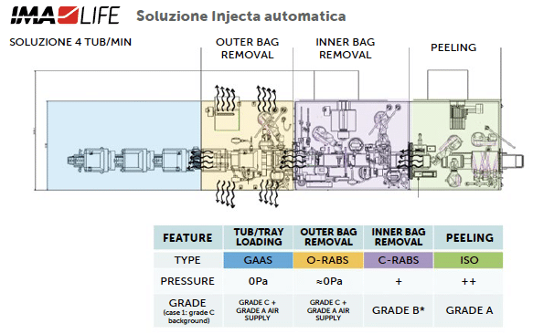
Figure 10b: workflow and barrier technology configurations for No-Touch-Transfer.
The key considerations for managing RTU packaging with a No-Touch Transfer (NTT) approach concerns RTU production site sterility assurance, transport safety to the production site and the overall aseptic process. At the production site, it is crucial to have comprehensive knowledge of the packaging process and materials, qualify the supplier and review their validation of sterilisation process. During transport, maintaining packaging integrity through proper logistics and shipment handling is essential. RTU suppliers will perform a shipping study to ensure that the packaging maintains its characteristics during transportation. Once in the aseptic processing area, integrity checks (ascertaining whether visual inspection is sufficient) and routine quality checks on tub and tray samples must be performed. The use of anthropomorphic robots in the introduction process with NTT is advantageous from the standpoint of container transport, which occurs without belt systems or contact-drag mechanisms, thereby minimising contamination in access areas to grade A. Thanks to the flexibility of robotic handling and the specific design of the docking system, the NTT process can be strengthened in various aspects:
Managing waste generated from the bags used to contain tubs and trays items is essential for minimising environmental impact and ensuring compliance with regulatory standards. These bags are typically made from materials like Tyvek and polyethylene. Once debagged, these single-use materials contribute to substantial waste, which companies are now focusing on handling more sustainably. Regulation (EU) 2025/40 on packaging and packaging waste, published in the Official Journal on 22/01/2021 and entering into force on 11/02/2025, whose pillars are rooted in the Circular Economy Plan, introduces the ‘Sustainability requirements’ for sustainable packaging. It embraces the goal of reducing the environmental impact of packaging and packaging waste in the European Union (EU), establishing a common framework for placement on the market, recovery, and recycling of packaging and packaging waste.
Figure 11: IMA LIFE NTT implementation supported by robotics.
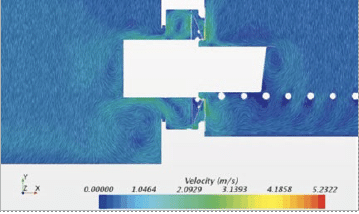
Figure 12: CFD simulation of tub extraction from protective bag in the docking station.
To promote the implementation of the regulation, economic operators, including producers, importers, distributors will have a range of obligations and responsibilities, including:
Optimisation note: Recycling RTU packaging presents challenges due to its mixed material composition, which often includes multi-layer barriers designed to prevent microbial contamination. This complex structure can make it difficult for traditional recycling facilities to process them effectively. However, some companies are working with specialised recycling partners capable of handling complex polymers. Medical packaging follows the key requirements of standards such as the ISO 11607 series, which requires a risk management approach that ensures that adverse events can be identified and corrective actions planned. Thus, traceability of the materials is fundamental, although tracing the sources of recycled materials is difficult.
Pharmaceutical companies often follow stringent protocols for disposing of RTU packaging bags, sealing lids, protective liners and plastic containers, when sterilising agents such as ETO are used. According to Annex III of directive 2008/98/EC, when waste contains one or more substances classified by one of the hazard-class, category codes and hazard statement codes, the waste will be assessed for HP 7, where appropriate and proportionate, according to test methods. If the presence of a substance, a mixture or an article indicates that the waste is carcinogenic, it shall be classified as hazardous by HP 7. The hazardous substance residual levels must meet the directive requirement for its classification as hazardous or non-hazardous waste to allow for disposal in the correct waste streams. This waste is segregated from general waste to ensure safe disposal. The bags are collected and processed according to standard waste management procedures, which may involve incineration, especially in facilities with integrated waste-to-energy systems. Incineration, although effective in reducing waste volume, has an environmental footprint, prompting companies to explore alternatives. EU waste and circular economy legislation trends foresee a change from pure waste law to holistic life cycle approaches, where producers become key actors with extended responsibility. Thus, producers are responsible for setting up and covering up the cost of convenient collection systems, transport, sorting and further processing of materials into either products or packaging. Producers, in instances of personal compliance with extended producer responsibility requirements, along with the designated producer responsibility organisations (PROs) or the operators handling packaging waste when public authorities manage the organisation of packaging waste, must ensure that packaging waste is collected separately, sorted, and recycled through existing infrastructure utilising recognised processes in a validated operational setting. The industry is exploring innovations to make RTU packaging more recyclable. This includes developing single-material barriers that provide the necessary protection but are easier to recycle. Additionally, RTU suppliers are investigating biodegradable or compostable alternatives that can break down more easily in controlled environments. Efforts to improve the sustainability of RTU packaging are ongoing, with RTU providers companies exploring closed-loop systems that enable the collection and recycling of used bags. Industry-wide collaborations and regulatory support are likely to play a crucial role in advancing these initiatives, making waste management of RTU packaging more environmentally friendly while maintaining the necessary standards for aseptic processing.
The surface decontamination process to introduce materials into a protected aseptic environment classified as grade A is typical for any material transfer chamber applied to isolators or cleanrooms. Therefore, the possibility of using this established approach to transfer material is considered a best practice with proven applicability in the pharmaceutical field. However, aspects of optimisation and innovation are present in the technological choice of the method used to achieve the surface reduction of the microbial load. Currently, there are mainly three strategies available on the market to achieve an acceptable level of microbiological risk reduction for an aseptic environment: the use of vaporised hydrogen peroxide, the use of UV or pulsed light, and the use of ionising radiation, specifically electrons (e-beam).
In this loading strategy, the tub enters the system already removed from its protective bags, allowing for simplification of the RTU packaging by reducing it from two layers to a single protective layer. This also reduces the precautions required during the initial debagging phase, which can be performed without the detailed attention outlined in NTT protocols, and in a lower-classified grade D environment.
In contrast to the packaging simplification, other technological challenges emerge that introduce a series of risks that must necessarily be analysed and assessed to properly manage surface decontamination methodologies:
Among the various solutions examined, it is possible to summarise a series of advantages and disadvantages that can be associated with the technological process.
VHP Decontamination using Large/Small Transfer Chambers
Advantages:
Possibility to manage different types of packaging
Validation up to 6-log microbiological reduction
Standard and consolidated VPHP-based technology
Room temperature process
Limitations
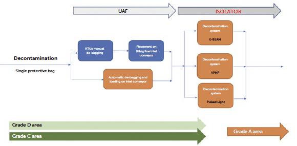
Figure 13: workflow of a surface decontamination strategy for tubs or trays introduction in grade A.
Slow process not suitable for fast tubs/trays throughput (up to 5/6 containers per minute requested by high-speed filling lines) due to batch processing timeRisks of H2O2 residues on primary container
Requalification in case of load or format change
Complex automation request for large batch automatic chamber loading-unloading
UV / Pulsed Light Decontamination
Advantages:
Limitations:
Electron Beam (E-beam) Decontamination
Advantages:
Limitations:
VHP decontamination using high-speed continuous tunnel
Advantages:
The VPHP decontamination using high-speed continuous tunnel is a new technology recently available. The primary objective was to replicate the strategic advantages of an E-beam tunnel by utilising traditional hydrogen peroxide-based decontamination methods. IMA LIFE has successfully adapted an existing technology from food processing, where high-concentration vaporised hydrogen peroxide (VPHP) exceeding 8000 PPM. By optimising the combination of temperature, high concentration and airflow distribution, it becomes feasible to achieve the 6-log decontamination time in approximately 30 seconds.
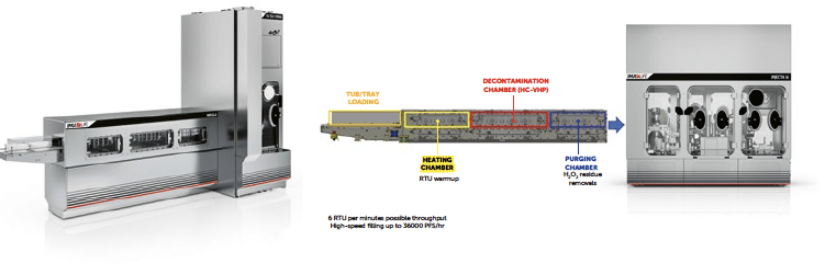
Figure 14: IMA LIFE Nebula solution for high-speed tubs or trays decontamination using HC-VPHP.
The process is divided into three chambers maintained at different pressures to achieve dynamic segregation of the VPHP within the machine and allowing for an ‘open’ process without a physical airtight separation between the decontaminated area and the external cleanroom environment. This approach enables the continuous operation of the decontamination tunnel where the RTU packaging passes through the three chambers moved by a simple roller-based conveyor system.
In decontamination methods, managing oxidant residuals is a critical challenge particularly caused by their potential impact on sensitive pharmaceutical products. Residuals can arise from decontaminants like hydrogen peroxide (H₂O₂) vapour or from high-energy processes such as electron beam (e-beam) systems that generate radicals and active Ozone. While effective for surface decontamination, these methods can leave residues of reactive substances, even at levels as low as parts per billion (ppb), which may oxidise or otherwise degrade sensitive pharmaceutical compounds.
Inside any kind of decontamination strategies (continuous and batch), issues may arise when trace H₂O₂ levels are detected inside the primary packaging of an injectable drug. This leads to degradation, which can be measured in stability studies and which has an impact on the shelf life of the final product. It is also possible to execute residues studies on tub or tray decontamination using sensitive analytical methods like “Red Amplex” or “Vacu-vials”. These tests leverage a colorimetric reaction to detect even low concentrations of hydrogen peroxide by utilising a redox-sensitive dye. To perform the test, a sample or swab is taken from the target surface and mixed with the” RedAmplex” / “Vacu-vials” reagent. The sample is then incubated for a specified period by allowing the colour to develop. The resulting colour is either visually assessed or measured using a spectrophotometer to quantify the hydrogen peroxide levels accurately.
This method is highly sensitive and enables the detection of very low residual levels (less than 100 ppb), making it suitable for environments that require strict control of hydrogen peroxide residues, such as pharmaceutical production areas or sterile facilities. Similar problems are generated by high-energy electron exposure, where ozone and radicals led to slight oxidation when in contact with certain types of drug formulations, even at ppb concentrations. As result, it is suggested to evaluate the material compatibility of packaging components with the RTU the tub is already stripped of its bags, thus reducing handling complexity and is simply moved via a roller conveyor. In some implementations the e-beam system includes up-and-down movements required for shielding, which can occasionally cause jams, though these issues are generally more limited compared to the fully robotic NTT systems.
• Sustainability. Sustainability aspects may favour a decontamination solution that reduces the protective packaging of RTU. A single-bag solution is possible if a decontamination system is in place whereas, with an NTT approach, regulatory requirements call for a double-bag solution which has a greater impact on the tub or tray cost and waste materials.
• Number of Support Operators. The support personnel required for a manual or semi-automatic NTT solution will be a critical factor. To maintain process times and high cadences necessary to feed the filler without interruptions, operators must be physically capable of quickly performing debagging operations in a classified environment protected by a glove barrier. Only in fully automated systems can the operator be limited to loading the RTU packaging onto the incoming conveyor belt. In the case of NTT, the operator is responsible for ensuring the correct positioning of the tub and trays and their protective bags, using stretching movements to smooth out any bag flaps. In a decontamination solution the operator de-bags the tub or tray before insertion in the machine, which is then loaded without requiring particular attention. Fully automated and continuous solutions are thus equivalent in terms of personnel effort, whereas semi-automatic or even manual solutions are challenging to align with large-scale production environments.
Risk of oxidising residues. The NTT and pulsed light solutions are completely free from this risk as they do not employ a sporicidal gas or an ionising source.
This approach thus entirely eliminates the risk, in contrast to a surface decontamination solution, which necessarily requires a precise assessment to address this issue.
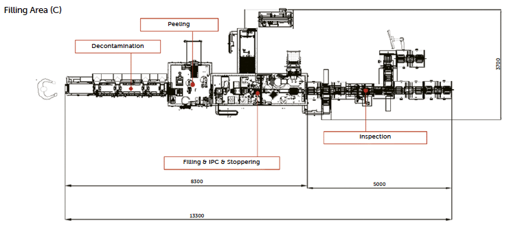
Figure 16: layout of Nebula with high-speed PFS fill-finish line. Note: in case of low-residue requirements due to sensitive products to H₂O₂ the line layout can consider an extra description chamber
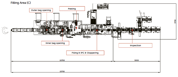
Figure 17: layout of robotized NTT with high-speed PFS fill-finish line.
Maintenance effort. The maintenance of robotic systems is simplified by the possibility of having identical anthropomorphic robots present in the facility, which, provided as off-the-shelf components, can be quickly replaced and simplify warehouse storage by requiring only a few units. From the end customers’ perspective, managing robots requires software specialists who are not always available in the engineering teams of pharmaceutical manufacturers; all of this may lead to training requests and an investment in training programs. Decontamination systems based on emitters, pulsed light or electrons are technologies subject to wear and tear, requiring periodic replacement. As a result, some models may incur consistent recurring costs. VPHP-based decontamination systems are generally similar to traditional generators integrated into isolators and typically do not experience major maintenance issues if supplied with H2O2 solutions that are adequate and validated by the provider.
![]()