menu

Pharma Website
Choose the market
blur_on
menu
An overview of design space construction.
Introduction
In pharmaceutical lyophilization, establishing a well-defined design space is essential for ensuring robust, scalable, and quality-driven processes. The design space represents a multidimensional relationship among critical input variables and process parameters that influence sublimation dynamics and, consequently, product quality and performance. Visualizing this relationship-such as mapping mass flow rate against chamber pressure-enables the identification of optimal operating conditions that maintain efficiency while mitigating risks like product collapse or choked flow. By integrating experimental data with modeling and simulation, a scientifically justified design space can be defined, ensuring process controllability and compliance with Quality by Design (QbD) principles. The following slides outline our approach to constructing this design space, emphasizing its practical applications in process development and scale-up.
What is a design space?
A design space is a graphical representation of various process parameters that influence the primary drying of a product, displaying regions that allow for efficient drying while staying within the bounds of the process. A design space is generally constructed as part of a quality by design (*QbD) cycle development project, supporting a first-principles-based and scientifically justified approach to cycle development and modification.
* Check our previous post for steps involved in a QbD cycle development project

What data do you need to make a design space?
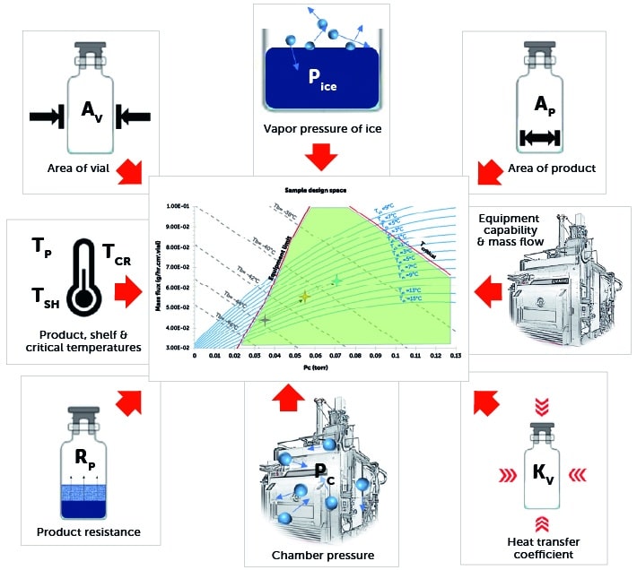
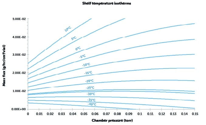
Constructing a design space – step 1
- Establish the relationship between chamber pressure and drying rate (mass flux) at a particular shelf temperature.
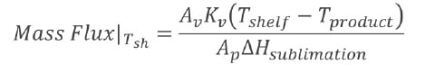
- Mass flux is calculated for each desired shelf temperature.
- Repeat for different values of shelf temperature.
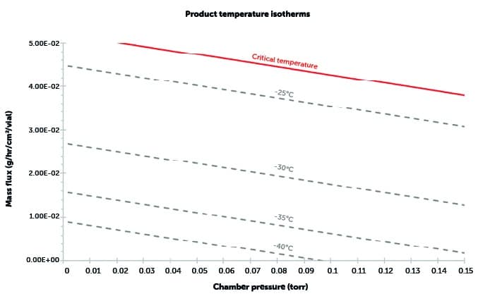
Constructing a design space – step 2
Construct product isotherms:
- At a range of shelf temperatures and chamber pressures, the values of product temperature at the bottom of the vial are calculated.

- Repeat for different values of product temperature.
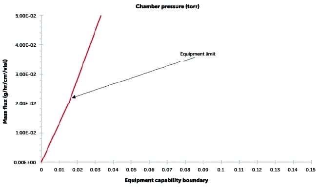
Constructing a design space – step 3
Add equipment capability boundary:
- Using either CFD modeling or a physical equipment characterisation test, the maximum mass flux that can be sustained by the lyophiliser is determined.
- The maximum sustainable mass flux is the equipment capability limit for that specific lyophiliser.
- All curves constructed thus far are combined to create the complete design space
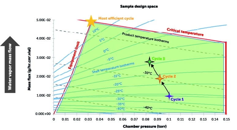
What does a design space let us know?
Green area denotes acceptable zone
![]()