Pharmakeyboard_arrow_rightEvaluation of Next-generation Container Closure Systems for Lyophilization Process Development.
menu

The global pharmaceutical manufacturing market size is predicted to grow at a compound annual growth rate (CAGR) of 11.3% between 2021 and 2028, with its current valuation pegged at $405.52 billion1. Consequently, the pharmaceutical packaging market is experiencing an unprecedented rise2 with its global market size currently valued at $107 billion at a CAGR of 9.4%. It is noteworthy that the US pharmaceutical packaging market alone accounted for $32.8 billion in 2019 at a 7.2% CAGR (Figure 1). With the advent of COVID-19, this growth trend is forecasted to accelerate further until 20283. However, these growth patterns have also led to a global surge in counterfeiting with the WHO estimating that 10% of medicines available globally are counterfeit4. One promising solution to curtail such malpractice is the introduction of tamper-evident container closure systems (CCS).
The idea of using anti-tampering devices is not a novel one, with regulations such as the Commission Delegated Regulation (EU) 2016/161 mandating drug manufacturers to add such devices to pharmaceutical products3. For example, crimping vials with aluminum caps is a current practice widely used for hermetically sealing glass vials5. However, relying on traditional vial crimping as an anti-tamper device is not a perfect solution due to known issues with closure integrity6, potential of metal particle contamination and inherent real estate costs associated with the installation of crimping stations outside lyo mechanical rooms7. The introduction of next-generation tamper-evident CCS eliminates all the aforementioned issues associated with a traditional vial crimping operation.
However, their impact on the lyo process remains a mystery and, therefore, it is vital to study their influence on the vapor mass flow during the lyophilization process. Previous studies have shown that the mass transfer resistance offered by the stopper can be 3-10% of the total mass transfer resistance as compared to the 80-90% resistance offered by the product itself8. However, due to the different engineering designs of competing next-generation tamper-evident CCS, it is critical to re-evaluate their influence on mass flow during the sublimation stage of a lyo process.
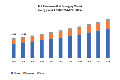
Figure 1. Growth trends in the US pharmaceutical packaging market3
An experimental study was designed to compare the mass flow differences between a conventional
vial & stopper assembly versus a next-generation tamper-evident CCS. Bisio Progetti’s next-generation ERON plastic caps were used as an industry-relevant example for this study. The three CCS compared were conventional lyo stoppers, ERON plastic caps with lyo stoppers and ERON plastic caps with serum stoppers. The two vial types included in this study were 2cc Schott vials and 3cc Ompi vials. Experimental Setup The study involved a total of three lyo cycles executed in IMA’s Lyofast 3 (2.3 m2) freeze dryer. Each cycle consisted of 850 2cc Schott vials and 850 3cc Ompi vials arranged on the bottom shelf of Lyofast 3 as per Figure 2 (also depicted in Figure 4, Figure 6 and Figure 7). 400 vials at the center of the shelf (highlighted in blue in Figure 2) were filled with 1 mL of WFI.
T-type thermocouples were used in the central vials to monitor the product temperature while a Tunable Diode Laser Absorption Spectrometer (TDLAS) was used to measure the mass flow rate in real time across all three cycles. Identical lyo recipes were used for all the cycles executed (Table 1).
In Cycle 1, the vials were partially stoppered using ERON caps fitted with lyo stoppers (Figure 3 and Figure 4). The aim of this cycle was to assess the influence of the ERON plastic cap on mass flow.
In Cycle 2, the vials were partially stoppered using ERON caps fitted with serum stoppers (Figure 5 and Figure 6). It is important to note that the use of serum stoppers alone is not possible as there are no partial stoppering position on serum stoppers. The aim of this cycle was to assess the mass flow difference between using ERON plastic caps with lyo stoppers or with serum stoppers.
In the final cycle, Cycle 3, the vials were partially stoppered with only lyo (conventional igloo) stoppers (Figure 7). This cycle served as the baseline cycle against which the effect of the ERON plastic caps on mass flow would be assessed.
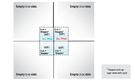
Figure 2. Vial arrangement used for each lyo cycle; TP = Temperature probe(s)
| Step # | Step Description |
Chamber Pressure (μbar) |
Shelf Temperature (°C) |
Time (hh:mm) |
| 1 | Freezing | 1 atm | -45 | 04:00 |
| 2 | Evacuation | 50 | -45 | ~01:00 |
| 3 | Drying | 50 | 0 | 03:00 |
| 4 | Drying | 100 | 0 | 02:00 |
| 5 | Drying | 150 | 0 | 02:00 |
Table 1. Lyo recipe executed across all cycles
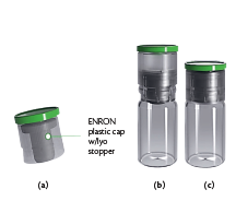
Figure 3. (a) ERON plastic cap fitter with a lyo stopper (b) Vial partially stoppered with ERON plastic cap and stopper (c) Vial fully stoppered with ERON plastic cap and stopper.
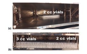
Figure 4. (a) Partially loaded shelf & (b) Fully loaded shelf of vials with lyo stoppers and ERON plastic caps.
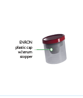
Figure 5. ERON plastic cap fitted with a serum stopper
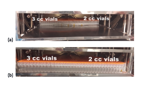
Figure 6. (a) Partially loaded shelf & (b) Fully loaded shelf of vials with serum stoppers and ERON plastic caps
Figure 7. (a) Partially loaded shelf & (b) Fully loaded shelf of vials with lyo stoppers only.
Mass flow rate values obtained via TDLAS during Cycles 1 (Figure 8), 2 and 3, are presented in Figure 9. The calculated average mass flow rate values per vial between Cycle 1 and Cycle 2 (serum stoppers with ERON plastic caps) demonstrated that vials partially stoppered with lyo stoppers and ERON plastic caps produced lower mass flow rates (to a maximum of 7.81% at 150 μbar) when compared with serum stopper loaded ERON plastic caps.
The effect of the ERON plastic cap alone can be determined by comparing mass flow rate values between Cycle 1 and Cycle 3 (lyo stoppers only); current testing indicates that addition of the ERON plastic caps on the lyo stoppers decreased the mass flow by up to a maximum of 9.43% (at 150 μbar).
The experiments described herein above were executed with the aim of deciphering the influence of a next-generation CCS on the sublimation mass flow, as compared to a conventional vial and stopper assembly. The results suggest that the ERON plastic caps offer a marginally increased resistance (9.43% at 150 μbar) to the vapor flow compared to a traditional lyo stopper. The lower mass flow rate can be attributed to partial shielding of the stopper vent area by the ERON plastic cap (Figure 3a). However, the inherent benefits offered by the ERON CCS clearly outweighs the observed change in sublimation mass flow. It is noteworthy that the resistance offered by ERON plastic caps, which are an integral part of the ERON CCS, were also influenced by the choice of stopper type, i.e., ERON CCS containing either a lyo stopper or a serum stopper. Lyo stopper loaded ERON caps had up to a maximum of 7.81% lower mass flow rate at 150 μbar when compared to a serum stopper loaded ERON cap. The better performance of the serum stopper loaded ERON CCS can be attributed to the larger vent area offered by the serum stopper when compared to a lyo stopper. This is evident when comparing results between using solely lyo stoppers and serum stopper loaded ERON caps; the mass flow in these cases are within 2.7% of each other on average. It is equally important to note that while serum stoppers are not traditionally preferred for lyophilization, their use becomes more viable when used in conjunction with the ERON CCS.
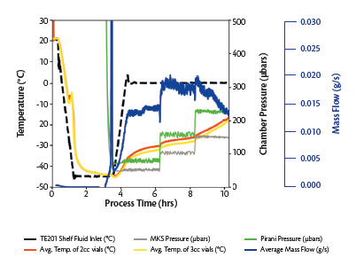
Figure 8. Lyo cycle data for cycle with lyo stoppers and ERON plastic caps.
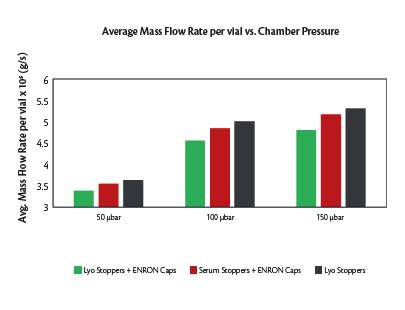
Figure 9. Mass flow rate results from all executed cycles.

The exclusive tech videos shot during Achema 2024 are now available on our dedicated website