Pharmakeyboard_arrow_rightDSMC Simulations of vapor flow and ice dynamics in a freeze dryer condenser
menu

Background and Motivation
Freeze-drying is a low-pressure, low-temperature condensation pumping process used in the manufacture of biological and pharmaceutical products. It involves a 3-stage process initiated by freezing (A-B), then reducing pressure below the triple point (B-C). Heat is then provided for sublimation of the ice in the primary drying (C-D). Performance of a freeze-dryer is governed by the vapor and ice dynamics in the low-pressure environment. One of the most important physical processes relevant to the freeze-dryer design is the formation of ice on the condensing surfaces during the drying stage. Non-uniform ice growth on the coils hinders the vapor trapping capability of the condenser. Understanding and controlling the ice build-up is needed for improved freeze-drying systems.
Objectives
Develop a comprehensive modeling framework for physics-based modeling of vapor flow and ice dynamics in freeze-drying.
Compare the model predictions with experimental measurements of freeze-dryer performance for laboratory and production scale. Determine critical design parameters for more efficient freeze-dryer systems and processes.
Methods
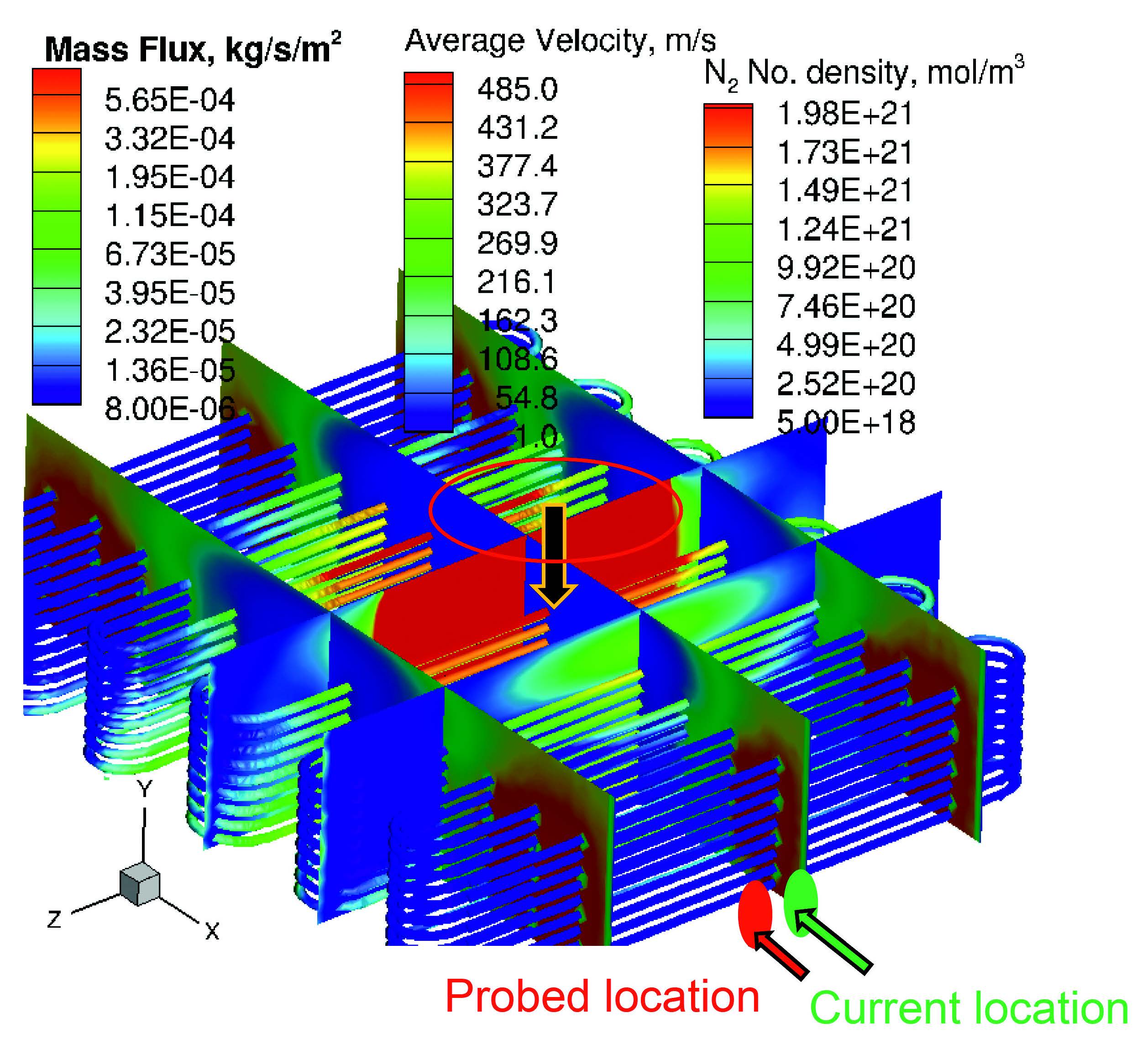
Numerical Simulations: Direct Simulation Monte Carlo (DSMC) techniques are applied to model relevant physical processes accompanying low-pressure vapor flow in the condenser. Low-temperature water vapor molecular model is used in the DSMC solver SMILE to simulate the flowfield structure. One of the most important physical processes relevant to condenser design is ice accretion on condensing coils. The developing ice front is tracked based on the mass flux computed at the nodes of the surface mesh.
Experimental Measurements: Ice accretion measurements in laboratory and industrial scale dryer under various loads and cycle parameters.
Effect of the Duct on Non-Uniformity
Simulation Parameters for Lyostar II: Mass Flow rate: 5 g/hr, Pure water-vapor, reservoir wall temperature: 273 K, surface mesh: 26,654 panels, sticking coefficient of 1 for coils. The presence of a duct between the product chamber and condenser increases non-uniformity by 65% at a sublimation rate of 5 g/hr Effect of Non-Condensable Gas and Tracking the Ice Growth over 24 hours Simulation Parameters for Lyostar II: Mass Flow rate: 55 g/hr, Multi Species: Water vapor and Nitrogen, reservoir wall temperature: 273 K, Sticking Coefficient of coils: 1 for water-vapor and 0 for N2, Duct pressure: 115 mTorr, Condenser Pressure, 70 mTorr
The presence of the non-condensable gas increases the resistance in the chamber. Thus, as the water-vapor enters the condenser chamber, it creates a narrow pocket around the duct exit where the water-vapor number density is highest and decreases away from it. Figure 4 presents the non-uniform ice accumulated on the coils over a period of 24 hours. The coils close to the duct exit have a maximum ice accumulation of 3.2 cm while that on the coil farthest away from the duct, drops to a mere 4 mm. The non-uniform ice growth can lead to a significant drop in the vapor trapping capability of the condenser.

Mass Flow rate: 55 g/hr, Chamber Pressure: 120 mTorr, Condenser Pressure:
70 mTorr, Total drying period: 1hour (left) and 24 hours (right), resulting in 1.1
mm growth rate per hour

at m= 55 g/hr, Ductpressure: 115 mTorr, Condenser Pressure, 70 mTorr